
TECHNICAL RESOURCES
Practical Optical Information for Imaging Applications
This resource section brings together technical explanations, frequently asked questions, reference diagrams, and selected legacy documentation related to Mosaic optical products and technologies.
RESOURCE AREAS
Information Organized Around the Optical Problem
Rather than maintaining separate resource libraries for every product family, the material here is organized around the optical concepts most likely to be useful when evaluating an imaging system.
Optical Anti-Aliasing
Sensor sampling, moiré, spatial aliasing, birefringent filtering, and the tradeoff between artifact suppression and retained image detail.
Polarization & Crystal Optics
Polarization state, retardance, birefringence, crystal orientation, and the optical behavior of materials such as quartz and lithium niobate.
Fabrication & Metrology
Optical finishing, thickness, wedge, orientation, surface condition, interferometric measurement, and other manufacturing considerations.
OPTICAL ANTI-ALIASING
Why Aliasing Begins Before Image Processing
A digital image sensor samples the optical image at discrete pixel locations. When scene detail contains spatial frequencies beyond what the sensor can represent correctly, false patterns or detail can appear.
An optical anti-aliasing filter modifies the image before sensor sampling. In birefringent designs, controlled optical displacement can distribute image information across neighboring sampling locations.
The useful filter strength depends on the complete imaging system, including sensor sampling, lens behavior, wavelength, scene content, and the amount of alias suppression required.
COMMON QUESTIONS
- Why does moiré appear?
- How does an optical low-pass filter work?
- How much filtering is appropriate?
- Does an OLPF simply blur the image?
- Why does sensor pixel pitch matter?
POLARIZATION & BIREFRINGENCE
Understanding Optical Behavior in Anisotropic Materials
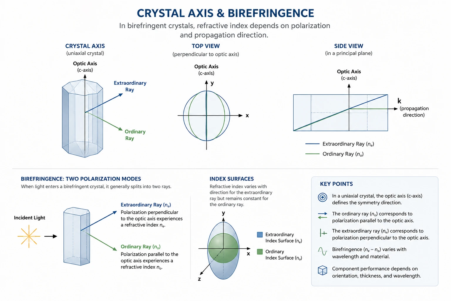
Birefringent materials respond differently to orthogonal polarization components. That property can be used to create controlled beam displacement, retardance, and polarization transformation.
Crystal orientation, thickness, wavelength, polarization direction, and material properties all contribute to the behavior of the finished optical component.
These effects form the basis for many crystal and polarization optics, including wave-retardation elements and birefringent filter components.
TECHNICAL QUESTIONS & ANSWERS
Frequently Asked Optical Questions
These answers are intended as general technical guidance. Specific component behavior depends on the material, wavelength, geometry, and imaging system.
What causes aliasing and moiré in a digital imaging system?
Aliasing occurs when spatial detail in the optical image exceeds what the sensor sampling grid can represent correctly. The sampled result can contain false patterns, false detail, or moiré that were not present in the original scene.
How does an optical anti-aliasing filter reduce aliasing?
An optical anti-aliasing filter modifies spatial information before the image reaches the sensor. Birefringent designs can create controlled image displacement that redistributes fine detail across neighboring sensor locations, reducing the strength of frequencies likely to alias.
Does an optical anti-aliasing filter just blur the image?
The purpose is not simply to create general blur. A properly selected filter modifies spatial information in a controlled way so that objectionable aliasing is reduced while useful image detail is retained as much as practical for the application.
What is polarization?
Polarization describes the orientation and phase relationship of the electric-field components of light. Optical elements can be used to select, rotate, or transform polarization depending on the requirements of the system.
What is the difference between linear and circular polarization?
In linearly polarized light, the electric field oscillates along a fixed direction. In circular polarization, orthogonal components have the appropriate amplitude and phase relationship for the field direction to rotate as the light propagates.
What does a wave plate or retardation element do?
A retardation element introduces a controlled phase difference between orthogonal polarization components. The resulting retardance depends on birefringence, thickness, wavelength, and orientation.
What is birefringence?
Birefringence is the difference in refractive index experienced by different polarization components in an anisotropic material. This can produce beam displacement, phase retardation, and other polarization-dependent effects.
Why is crystal orientation important?
Optical behavior in a birefringent crystal depends on the relationship between light propagation, polarization, and the crystal's optical axes. The same external geometry can behave differently if the crystal orientation changes.
Why are quartz and lithium niobate useful optical materials?
Both materials possess optical anisotropy and birefringence that can be useful in polarization and specialized optical components. Material selection depends on wavelength, geometry, required optical behavior, and manufacturing considerations.
Why do thickness and wedge matter in an optical component?
Thickness can directly affect optical path length, retardance, or beam displacement. Wedge and parallelism can affect beam direction, interference effects, assembly geometry, and system performance.
What is interferometric optical measurement?
Interferometry compares optical wavefronts to reveal small differences in optical path. Depending on the setup, it can be used to evaluate characteristics such as optical flatness or transmitted wavefront behavior.
What information is useful when asking about a custom optic?
Useful starting information can include the required optical function, wavelength, sensor or imaging-system information, component dimensions, material requirements, polarization, available optical space, existing drawings, and example images showing the problem.
FABRICATION & MEASUREMENT
Optical Performance Depends on How the Component Is Made
Material, geometry, orientation, surface preparation, polishing, and measurement all contribute to the performance of a precision optical component.
Thickness
Thickness can influence optical path, retardance, displacement, packaging, and the mechanical geometry of the component.
Wedge & Parallelism
Relative surface orientation can influence transmitted beam direction and the way the optic interacts with the rest of the system.
Surface Quality
Surface preparation and polishing affect scattering, wavefront quality, optical interfaces, and the condition of the finished optic.
Metrology
Measurement during fabrication provides feedback and helps verify the characteristics most important to the intended optical function.
REFERENCE MATERIAL
Technical Notes and Reference Diagrams
Additional technical notes, application guides, diagrams, and reference material can be added here as useful documentation becomes available.
Technical Notes
Short technical explanations covering optical concepts, manufacturing considerations, or product-related topics.
Application Guides
Practical guidance for evaluating optical anti-aliasing, polarization, crystal optics, and imaging-system integration.
Reference Diagrams
Educational diagrams illustrating optical concepts and component behavior without exposing proprietary customer designs.
LEGACY DOCUMENTATION
Archived Information From Earlier Mosaic Optical Products
Selected historical documentation may be preserved because it remains useful for existing equipment, technical reference, or understanding earlier Mosaic optical products.
ARCHIVE NOTICE
Legacy documentation may describe products, configurations, specifications, certifications, or services that are no longer offered in their original form.
Inclusion in this archive should not be interpreted as confirmation of current product availability or current compliance status. For present capabilities or replacement options, contact Mosaic Optoelectronics directly.
Product Documentation
Historical manuals, brochures, specifications, drawings, or other published product information may be preserved here when appropriate.
Technical Reference
Older technical explanations may remain useful when they accurately describe optical principles or previously supplied components.
Replacement Questions
If you are working with an older Mosaic optical product, provide any model, drawing, documentation, photographs, or available component information when contacting us.
HAVE A TECHNICAL QUESTION?
You Do Not Need to Have the Optical Solution Already Defined
If you are seeing an imaging artifact, dealing with reflections, evaluating a crystal component, or trying to reproduce an existing optic, start with the information you have.
Images, sketches, sample components, sensor information, drawings, wavelength information, or a description of the problem can all help begin the discussion.
USEFUL INFORMATION
- What you are trying to image or measure
- The optical problem you are seeing
- Example images or photographs
- Sensor and lens information
- Wavelength or spectral range
- Existing component drawings or dimensions
- Material information, if known
- Prototype or quantity requirements
TECHNICAL SUPPORT
Have a Question About an Optical Component or Imaging Problem?
Share the information you have. We can help determine which optical concepts, product family, or manufacturing approach may be relevant.